Cloudflare Workflows — это механизм устойчивого выполнения, который позволяет объединять шаги в цепочки, повторять попытки при сбое и сохранять состояние в рамках длительных процессов. Разработчики используют Workflows для создания фоновых агентов, управления конвейерами данных, построения систем согласования с участием человека и многого другого.
В прошлом месяце мы анонсировали, что у каждого рабочего процесса (workflow), развернутого в Cloudflare, теперь есть полная визуальная диаграмма в панели управления.
Мы создали эту функцию, потому что возможность визуализировать ваши приложения сейчас важнее, чем когда-либо. Кодирующие агенты пишут код, который вы можете читать, а можете и не читать. Однако структура того, что строится, по-прежнему имеет значение: как шаги соединяются, где они ветвятся и что на самом деле происходит.
Если вы раньше видели диаграммы из визуальных конструкторов рабочих процессов, они обычно работают на основе чего-то декларативного: JSON-конфигураций, YAML, перетаскивания. Однако Cloudflare Workflows — это просто код. Они могут включать Promises, Promise.all, циклы, условные конструкции и/или быть вложенными в функции или классы. Эта динамическая модель выполнения делает отрисовку диаграммы немного более сложной.
Мы используем абстрактные синтаксические деревья (AST), чтобы статически вывести граф, отслеживая отношения Promise и await, чтобы понять, что выполняется параллельно, что блокирует выполнение и как части связаны между собой.
Читайте дальше, чтобы узнать, как мы создали эти диаграммы, или разверните свой первый рабочий процесс и увидите диаграмму своими глазами.
Вот пример диаграммы, сгенерированной из кода Cloudflare Workflows:

Динамическое выполнение рабочего процесса
Как правило, механизмы выполнения рабочих процессов могут работать либо по динамическому, либо по последовательному (статическому) порядку. Последовательное выполнение может казаться более интуитивно понятным решением: запуск рабочего процесса → шаг A → шаг B → шаг C, где шаг B начинает выполняться сразу после завершения механизмом шага A, и так далее.
Cloudflare Workflows следуют динамической модели выполнения. Поскольку рабочие процессы — это просто код, шаги выполняются по мере того, как среда выполнения (runtime) встречает их. Когда среда выполнения обнаруживает шаг, он передается механизму рабочего процесса, который управляет его выполнением. Шаги по своей природе не являются последовательными, если их выполнение не ожидается (awaited) — механизм выполняет все неожидаемые шаги параллельно. Таким образом, вы можете писать код рабочего процесса как поток управления без дополнительных оберток или директив. Вот как работает передача управления:
-
Запускается механизм (engine) — «супервизор» Durable Object для этого экземпляра. Механизм отвечает за логику фактического выполнения рабочего процесса.
-
Механизм запускает пользовательский воркер через динамическую диспетчеризацию, передавая управление среде выполнения Workers.
-
Когда среда выполнения встречает
step.do, она передает выполнение обратно механизму. -
Механизм выполняет шаг, сохраняет результат (или, если применимо, генерирует ошибку) и снова запускает пользовательский Worker.
При такой архитектуре механизм изначально не «знает» порядок шагов, которые он выполняет, — но для диаграммы порядок шагов становится crucial информацией. Задача здесь заключается в том, чтобы точно преобразовать подавляющее большинство рабочих процессов в диагностически полезный граф; пока диаграммы находятся в бета-версии, мы продолжим итеративно улучшать эти представления.
Разбор кода
Получение скрипта во время развертывания (deploy time), а не во время выполнения (run time), позволяет нам проанализировать рабочий процесс целиком, чтобы статически сгенерировать диаграмму.
Отступив на шаг назад, вот жизненный цикл развертывания рабочего процесса:
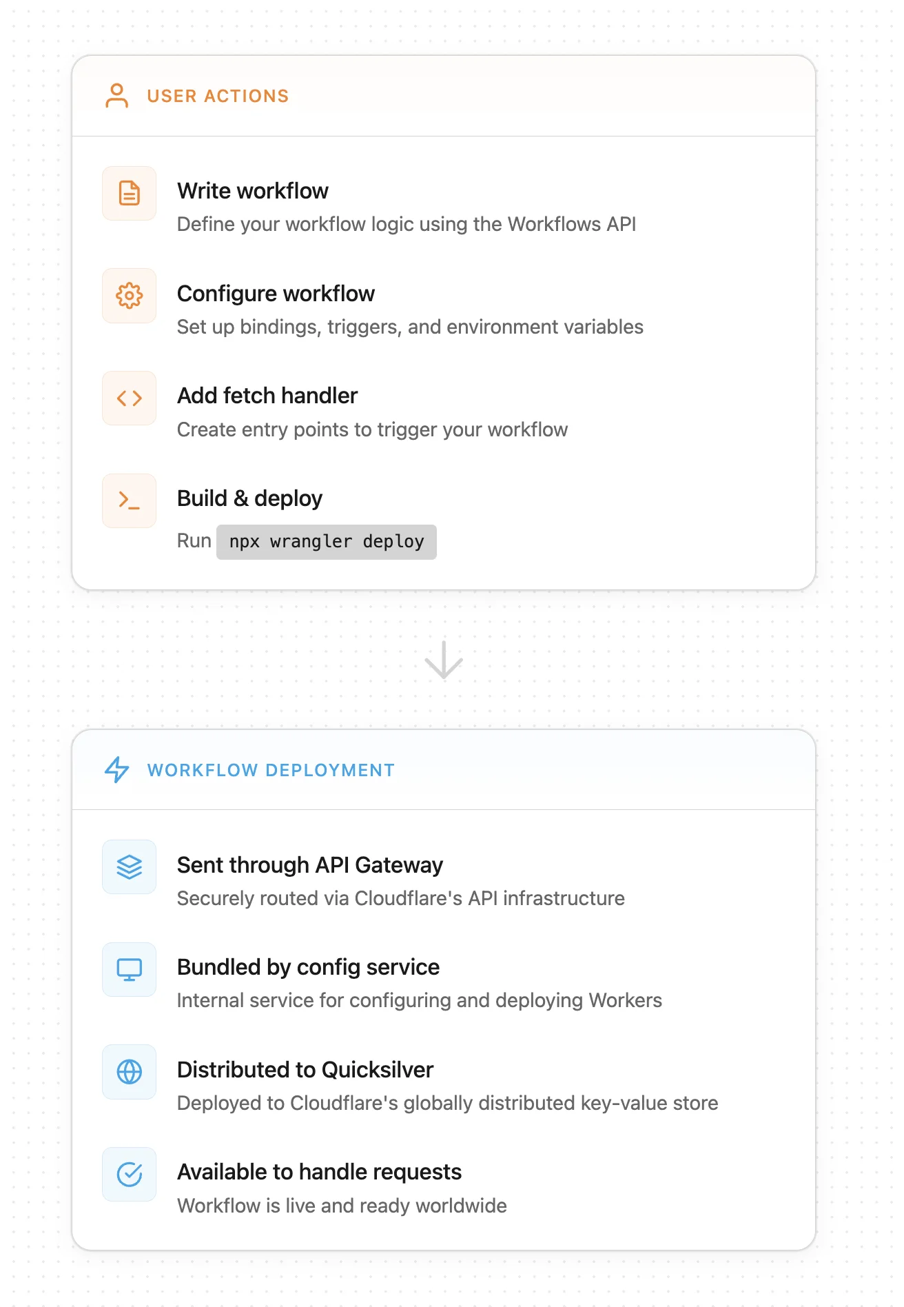
Чтобы создать диаграмму, мы получаем скрипт после того, как он был собран (bundled) внутренней службой конфигурации, которая развертывает Workers (шаг 2 под «Workflow deployment»). Затем мы используем парсер для создания абстрактного синтаксического дерева (AST), представляющего рабочий процесс, и наша внутренняя служба генерирует и обходит промежуточный граф со всеми WorkflowEntrypoints и вызовами шагов рабочего процесса. Мы отрисовываем диаграмму на основе конечного результата в нашем API.
Когда Worker развертывается, служба конфигурации собирает (по умолчанию с помощью esbuild) и минифицирует код, если не указано иное. Это создает еще одну сложность — хотя Workflows на TypeScript следуют интуитивно понятной схеме, их минифицированный JavaScript (JS) может быть плотным и трудным для восприятия. Существуют также различные способы минификации кода в зависимости от сборщика (bundler).
Вот пример кода Workflow, который показывает параллельное выполнение агентов:
const summaryPromise = step.do(
         `summary agent (loop ${loop})`,
         async () => {
           return runAgentPrompt(
             this.env,
             SUMMARY_SYSTEM,
             buildReviewPrompt(
               'Суммируйте этот текст в 5 пунктах.',
               draft,
               input.context
             )
           );
         }
       );
        const correctnessPromise = step.do(
         `correctness agent (loop ${loop})`,
         async () => {
           return runAgentPrompt(
             this.env,
             CORRECTNESS_SYSTEM,
             buildReviewPrompt(
               'Перечислите проблемы корректности и предложите исправления.',
               draft,
               input.context
             )
           );
         }
       );
        const clarityPromise = step.do(
         `clarity agent (loop ${loop})`,
         async () => {
           return runAgentPrompt(
             this.env,
             CLARITY_SYSTEM,
             buildReviewPrompt(
               'Перечислите проблемы ясности и предложите исправления.',
               draft,
               input.context
             )
           );
         }
       );
При сборке с помощью rspack фрагмент минифицированного кода выглядит так:
class pe extends e{async run(e,t){de("workflow.run.start",{instanceId:e.instanceId});const r=await t.do("validate payload",async()=>{if(!e.payload.r2Key)throw new Error("r2Key is required");if(!e.payload.telegramChatId)throw new Error("telegramChatId is required");return{r2Key:e.payload.r2Key,telegramChatId:e.payload.telegramChatId,context:e.payload.context?.trim()}}),s=await t.do("load source document from r2",async()=>{const e=await this.env.REVIEW_DOCUMENTS.get(r.r2Key);if(!e)throw new Error(`R2 object not found: ${r.r2Key}`);const t=(await e.text()).trim();if(!t)throw new Error("R2 object is empty");return t}),n=Number(this.env.MAX_REVIEW_LOOPS??"5"),o=this.env.RESPONSE_TIMEOUT??"7 days",a=async(s,i,c)=>{if(s>n)return le("workflow.loop.max_reached",{instanceId:e.instanceId,maxLoops:n}),await t.do("notify max loop reached",async()=>{await se(this.env,r.telegramChatId,`Review stopped after ${n} loops for ${e.instanceId}. Start again if you still need revisions.`)}),{approved:!1,loops:n,finalText:i};const h=t.do(`summary agent (loop ${s})`,async()=>te(this.env,"You summarize documents. Keep the output short, concrete, and factual.",ue("Summarize this text in 5 bullet points.",i,r.context)))...Или, при сборке с помощью vite, вот минифицированный фрагмент:
class ht extends pe {
  async run(e, r) {
    b("workflow.run.start", { instanceId: e.instanceId });
    const s = await r.do("validate payload", async () => {
      if (!e.payload.r2Key)
        throw new Error("r2Key is required");
      if (!e.payload.telegramChatId)
        throw new Error("telegramChatId is required");
      return {
        r2Key: e.payload.r2Key,
        telegramChatId: e.payload.telegramChatId,
        context: e.payload.context?.trim()
      };
    }), n = await r.do(
      "load source document from r2",
      async () => {
        const i = await this.env.REVIEW_DOCUMENTS.get(s.r2Key);
        if (!i)
          throw new Error(`R2 object not found: ${s.r2Key}`);
        const c = (await i.text()).trim();
        if (!c)
          throw new Error("R2 object is empty");
        return c;
      }
    ), o = Number(this.env.MAX_REVIEW_LOOPS ?? "5"), l = this.env.RESPONSE_TIMEOUT ?? "7 days", a = async (i, c, u) => {
      if (i > o)
        return H("workflow.loop.max_reached", {
          instanceId: e.instanceId,
          maxLoops: o
        }), await r.do("notify max loop reached", async () => {
          await J(
            this.env,
            s.telegramChatId,
            `Review stopped after ${o} loops for ${e.instanceId}. Start again if you still need revisions.`
          );
        }), {
          approved: !1,
          loops: o,
          finalText: c
        };
      const h = r.do(
        `summary agent (loop ${i})`,
        async () => _(
          this.env,
          et,
          K(
            "Summarize this text in 5 bullet points.",
            c,
            s.context
          )
        )
      )...
Minified code can get pretty gnarly — and depending on the bundler, it can get gnarly in a bunch of different directions.
We needed a way to parse the various forms of minified code quickly and precisely. We decided oxc-parser from the JavaScript Oxidation Compiler (OXC) was perfect for the job. We first tested this idea by having a container running Rust. Every script ID was sent to a Cloudflare Queue, after which messages were popped and sent to the container to process. Once we confirmed this approach worked, we moved to a Worker written in Rust. Workers supports running Rust via WebAssembly, and the package was small enough to make this straightforward.
The Rust Worker is responsible for first converting the minified JS into AST node types, then converting the AST node types into the graphical version of the workflow that is rendered on the dashboard. To do this, we generate a graph of pre-defined node types for each workflow and translate into our graph representation through a series of node mappings.
Rendering the diagram
There were two challenges to rendering a diagram version of the workflow: how to track step and function relationships correctly, and how to define the workflow node types as simply as possible while covering all the surface area.
To guarantee that step and function relationships are tracked correctly, we needed to collect both the function and step names. As we discussed earlier, the engine only has information about the steps, but a step may be dependent on a function, or vice versa. For example, developers might wrap steps in functions or define functions as steps. They could also call steps within a function that come from different modules or rename steps.
Although the library passes the initial hurdle by giving us the AST, we still have to decide how to parse it. Some code patterns require additional creativity. For example, functions — within a WorkflowEntrypoint, there can be functions that call steps directly, indirectly, or not at all. Consider functionA, which contains console.log(await functionB(), await functionC()) where functionB calls a step.do(). In that case, both functionA and functionB should be included on the workflow diagram; however, functionC should not. To catch all functions which include direct and indirect step calls, we create a subgraph for each function and check whether it contains a step call itself or whether it calls another function which might. Those subgraphs are represented by a function node, which contains all of its relevant nodes. If a function node is a leaf of the graph, meaning it has no direct or indirect workflow steps within it, it is trimmed from the final output.
We check for other patterns as well, including a list of static steps from which we can infer the workflow diagram or variables, defined in up to ten different ways. If your script contains multiple workflows, we follow a similar pattern to the subgraphs created for functions, abstracted one level higher.
For every AST node type, we had to consider every way they could be used inside of a workflow: loops, branches, promises, parallels, awaits, arrow functions… the list goes on. Even within these paths, there are dozens of possibilities. Consider just a few of the possible ways to loop:
// for...of
for (const item of items) {
	await step.do(`process ${item}`, async () => item);
}
// while
while (shouldContinue) {
	await step.do('poll', async () => getStatus());
}
// map
await Promise.all(
	items.map((item) => step.do(`map ${item}`, async () => item)),
);
// forEach
await items.forEach(async (item) => {
	await step.do(`each ${item}`, async () => item);
});
And beyond looping, how to handle branching:
// switch / case
switch (action.type) {
	case 'create':
		await step.do('handle create', async () => {});
		break;
	default:
		await step.do('handle unknown', async () => {});
		break;
}

// if / else if / else
if (status === 'pending') {
	await step.do('pending path', async () => {});
} else if (status === 'active') {
	await step.do('active path', async () => {});
} else {
	await step.do('fallback path', async () => {});
}

// ternary operator
await (cond
	? step.do('ternary true branch', async () => {})
	: step.do('ternary false branch', async () => {}));

// nullish coalescing with step on RHS
const myStepResult =
	variableThatCanBeNullUndefined ??
	(await step.do('nullish fallback step', async () => 'default'));

// try/catch with finally
try {
	await step.do('try step', async () => {});
} catch (_e) {
	await step.do('catch step', async () => {});
} finally {
	await step.do('finally step', async () => {});
}
Our goal was to create a concise API that communicated what developers need to know without overcomplicating it. But converting a workflow into a diagram meant accounting for every pattern (whether it follows best practices, or not) and edge case possible. As we discussed earlier, each step is not explicitly sequential, by default, to any other step. If a workflow does not utilize await and Promise.all(), we assume that the steps will execute in the order in which they are encountered. But if a workflow included await, Promise or Promise.all(), we needed a way to track those relationships.
We decided on tracking execution order, where each node has a starts: and resolves: field. The starts and resolves indices tell us when a promise started executing and when it ends relative to the first promise that started without an immediate, subsequent conclusion. This correlates to vertical positioning in the diagram UI (i.e., all steps with starts:1 will be inline). If steps are awaited when they are declared, then starts and resolves will be undefined, and the workflow will execute in the order of the steps’ appearance to the runtime.
While parsing, when we encounter an unawaited Promise or Promise.all(), that node (or nodes) are marked with an entry number, surfaced in the starts field. If we encounter an await on that promise, the entry number is incremented by one and saved as the exit number (which is the value in resolves). This allows us to know which promises run at the same time and when they’ll complete in relation to each other.
export class ImplicitParallelWorkflow extends WorkflowEntrypoint<Env, Params> {
 async run(event: WorkflowEvent<Params>, step: WorkflowStep) {
   const branchA = async () => {
     const a = step.do("task a", async () => "a"); //starts 1
     const b = step.do("task b", async () => "b"); //starts 1
     const c = await step.waitForEvent("task c", { type: "my-event", timeout: "1 hour" }); //starts 1 resolves 2
     await step.do("task d", async () => JSON.stringify(c)); //starts 2 resolves 3
     return Promise.all([a, b]); //resolves 3
   };

   const branchB = async () => {
     const e = step.do("task e", async () => "e"); //starts 1
     const f = step.do("task f", async () => "f"); //starts 1
     return Promise.all([e, f]); //resolves 2
   };

   await Promise.all([branchA(), branchB()]);

   await step.sleep("final sleep", 1000);
 }
}
You can see the steps’ alignment in the diagram:

After accounting for all of those patterns, we settled on the following list of node types:
| StepSleep
| StepDo
| StepWaitForEvent
| StepSleepUntil
| LoopNode
| ParallelNode
| TryNode
| BlockNode
| IfNode
| SwitchNode
| StartNode
| FunctionCall
| FunctionDef
| BreakNode;
Вот несколько примеров вывода API для различных поведений:
function call:
{
  "functions": {
    "runLoop": {
      "name": "runLoop",
      "nodes": []
    }
  }
}
Условная конструкция if, ветвящаяся в step.do:
{
  "type": "if",
  "branches": [
    {
      "condition": "loop > maxLoops",
      "nodes": [
        {
          "type": "step_do",
          "name": "notify max loop reached",
          "config": {
            "retries": {
              "limit": 5,
              "delay": 1000,
              "backoff": "exponential"
            },
            "timeout": 10000
          },
          "nodes": []
        }
      ]
    }
  ]
}
parallel с step.do и waitForEvent:
{
  "type": "parallel",
  "kind": "all",
  "nodes": [
    {
      "type": "step_do",
      "name": "correctness agent (loop ${...})",
      "config": {
        "retries": {
          "limit": 5,
          "delay": 1000,
          "backoff": "exponential"
        },
        "timeout": 10000
      },
      "nodes": [],
      "starts": 1
    },
...
    {
      "type": "step_wait_for_event",
      "name": "wait for user response (loop ${...})",
      "options": {
        "event_type": "user-response",
        "timeout": "unknown"
      },
      "starts": 3,
      "resolves": 4
    }
  ]
}
Что дальше
В конечном счете, цель этих диаграмм Workflow — служить полнофункциональным инструментом отладки. Это означает, что вы сможете:
-
Отслеживать выполнение через граф в реальном времени
-
Обнаруживать ошибки, ожидать одобрения человеком (human-in-the-loop) и пропускать шаги для тестирования
-
Получить доступ к визуализациям в локальной разработке